Key Features
- Frequency Range 0.2 - 24 GHz
- Gain 14 dB
- P1dB 22.5 dBm
- IP3 36 dBm
- Supply Single
- On-chip DC Block Capacitors
- compact size5x5 mm
Applications
- Wideband Receivers
- Telecommunication
- Test and Measurement
- SATCOM
- SDR
Architecture
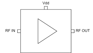
ATEK569P5 Block Diagram
ATEK569P5 is a wideband driver amplifier covering 0.2 to 24 GHz frequency range. ATEK569P5 provides flat gain with single supply voltage. This allows users to easily realize wideband receiver frontends. Amplifier housed in compact 5x5 mm low cost SMD package, input and output matched to 50 ohms internally. Evaluation Board, bare die, custom package, and module options are available upon request.
Technical Specifications
| Parameter | Condition | Min | Typical | Max | Unit |
|---|---|---|---|---|---|
| Frequency Range | 0.2 | 24 | GHz | ||
| Gain | 0.25 GHz | 13.8 | dB | ||
| 2 GHz | 13.4 | dB | |||
| 8 GHz | 13.4 | dB | |||
| 12 GHz | 13.1 | dB | |||
| 18 GHz | 13.9 | dB | |||
| 24 GHz | 12.2 | dB | |||
| Isolation | 0.25 GHz | 60 | dB | ||
| 2 GHz | 52 | dB | |||
| 8 GHz | 38 | dB | |||
| 12 GHz | 34 | dB | |||
| 18 GHz | 27 | dB | |||
| 24 GHz | 25 | dB | |||
| Input Return Loss | -20 | dB | |||
| Output Return Loss | -15 | dB | |||
| Noise Figure | 3 | dB | |||
| Output IP3 | 36 | dBm | |||
| Output P1dB | 22.5 | dBm | |||
| Psat | 25 | dBm | |||
| DC Supply Voltage | 10 | 12 | V | ||
| DC Supply Current | 150 | 160 | mA | ||
| Operating Temperature | -40 | 85 | °C |
Available Resources
Ready to Integrate ATEK569P5?
Contact our engineering team for technical support, samples, or volume pricing.
Request More Information