Key Features
- Frequency Range 485 - 8000 MHz
- 7 Switchable Band Pass Filters
- Input IP3 43 dBm
- Supply 3.3 V to 5 V
Applications
- Test Equipment
- Electronic Warfare
- Wideband Receivers
- Spectrum Analysis
- SDR
Architecture
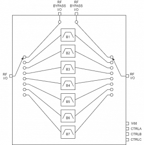
ATEK950P6 Block Diagram
ATEK950P6 is a wideband switchable filter bank covering 485 MHz to 8000 MHz with seven independently selectable bandpass filter paths. The module features low insertion loss, high linearity (43 dBm IIP3), and fast switching speed of 150 nS. Single supply operation from 3.3V to 5V with logic-level switching control makes it ideal for test equipment, spectrum analysis, electronic warfare systems, and software-defined radio applications.
Technical Specifications
| Parameter | Condition | Min | Typical | Max | Unit |
|---|---|---|---|---|---|
| Frequency Range | 2 | 8000 | MHz | ||
| 3dB Bandwidth | Band 1 | 485 - 810 | MHz | ||
| Band 2 | 670 - 1125 | MHz | |||
| Band 3 | 960 - 1670 | MHz | |||
| Band 4 | 1440 - 2560 | MHz | |||
| Band 5 | 2140 - 3850 | MHz | |||
| Band 6 | 3300 - 5880 | MHz | |||
| Band 7 | 4820 - 8500 | MHz | |||
| External Path | 2-9000 | MHz | |||
| Insertion Loss | Filter Paths | 6 | dB | ||
| External Path | 3 | dB | |||
| Input IP3 | 43 | dBm | |||
| Input P1dB | 27.5 | dBm | |||
| Switching Speed | 150 | nS | |||
| Control Level | Low | -0.1 | 0.5 | V | |
| High | 2 | 5 | V | ||
| DC Supply Voltage | 3.2 | 5 | 5.5 | V | |
| DC Supply Current | 15 | mA | |||
| Operating Temperature | -40 | 85 | °C |
Ready to Integrate ATEK950P6?
Contact our engineering team for technical support, samples, or volume pricing.
Request More Information