Key Features
- Frequency Range 2 - 18 GHz
- 6 Switchable Band Pass Filters
- Input IP3 33 dBm
- compact size5x5 mm
Applications
- Wideband Receivers
- Telecommunication
- Test and Measurement
- SATCOM
- SDR
Architecture
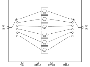
ATEK656N5 Block Diagram
Technical Specifications
| Parameter | Condition | Min | Typical | Max | Unit |
|---|---|---|---|---|---|
| Frequency Range | 2 | 18 | GHz | ||
| 3dB Bandwidth | Band 1 | 1,9 - 3,5 | GHz | ||
| Band 2 | 2,8 - 5,4 | GHz | |||
| Band 3 | 4,5 - 9,1 | GHz | |||
| Band 4 | 7,1 - 12,3 | GHz | |||
| Band 5 | 9,9 - 15,3 | GHz | |||
| Band 6 | 12,5 - 18 | GHz | |||
| Insertion Loss | Band 1 | 7.5 | dB | ||
| Band 2 | 6.5 | dB | |||
| Band 3 | 6.5 | dB | |||
| Band 4 | 7.5 | dB | |||
| Band 5 | 9 | dB | |||
| Band 6 | 9 | dB | |||
| Input Return Loss | -12 | dB | |||
| Output Return Loss | -10 | dB | |||
| Input IP3 | 33 | dBm | |||
| Input P1dB | 23 | dBm | |||
| Switching Time | On | 120 | ns | ||
| Off | 25 | ns | |||
| DC Supply Voltage | -5 | V | |||
| DC Supply Current | 12 | mA | |||
| Control Level | Low | 0 | V | ||
| High | -5 | V | |||
| Operating Temperature | -40 | 85 | °C |
Available Resources
Ready to Integrate ATEK656N5?
Contact our engineering team for technical support, samples, or volume pricing.
Request More Information