Key Features
- Frequency Range DC to 40+ GHz
- Low Loss 0.8 dB @ 40 GHz
- 22 dB Return Loss at 40 GHz
- Solder free interconnect
- compact size
Applications
- WidebandRF/MicrowaveSystems
- Evaluation Boards
- RF Test Systems
- Telecommunication
Architecture
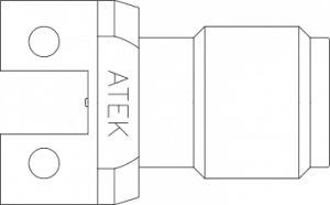
ATEK9292 Block Diagram
ATEK9292 is a 2.92mm/K PCB End-Launch connector operating to 40 GHz and above, supporting Microwave and mmWave applications covering 5G and Ka-Band SATCOM frequencies. ATEK9292 provides better than 20 dB return loss up to 40 GHz and beyond, enabling Ka-Band telecommunication applications. Easy installation does not require soldering, allowing the connector to be easily re-used on multiple evaluation applications. Precision manufacturing of the connectors enables superior electrical and RF performance. Evaluation Board for evaluating connector performance is available upon request.
Technical Specifications
| Parameter | Condition | Min | Typical | Max | Unit |
|---|---|---|---|---|---|
| Frequency Range | DC | 40+ | GHz | ||
| Insertion Loss | 5 GHz | -0.15 | dB | ||
| 10 GHz | -0.25 | dB | |||
| 20 GHz | -0.43 | dB | |||
| 30 GHz | -0.68 | dB | |||
| 40 GHz | -0.82 | -1 | dB | ||
| Input Return Loss | 5 GHz | -29 | dB | ||
| 10 GHz | -30 | dB | |||
| 20 GHz | -34 | dB |
Available Resources
Ready to Integrate ATEK9292?
Contact our engineering team for technical support, samples, or volume pricing.
Request More Information