Key Features
- Frequency Range 4 - 10 GHz
- Gain 15 dB
- Supply Single
- compact size3x3 mm
Applications
- Wideband Receivers
- Telecommunication
- SATCOM
- SDR
- Test Equipment
- Radar
Architecture
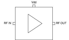
ATEK561P3 Block Diagram
ATEK561P3 is an RF amplifier covering 4 to 10 GHz frequency range. Amplifier is biased with a single positive supply, input and outputs are matched to 50 ohms internally, has internal DC block capacitors. These features allow users to easily integrate the amplifier into RF transmit receive chains. Amplifier housed in compact 3x3 mm low cost SMD package. Evaluation Board, custom package, and module options are available upon request.
Technical Specifications
| Parameter | Condition | Min | Typical | Max | Unit |
|---|---|---|---|---|---|
| Frequency Range | 4 | 10 | GHz | ||
| Small Signal Gain | 4 GHz | 13.6 | dB | ||
| 6 GHz | 16 | dB | |||
| 8 GHz | 16.3 | dB | |||
| 10 GHz | 14.2 | dB | |||
| Isolation | 4 GHz | -48 | dB | ||
| 6 GHz | -52 | dB | |||
| 8 GHz | -46 | dB | |||
| 10 GHz | -49 | dB | |||
| Input Return Loss | -14 | dB |
Available Resources
Ready to Integrate ATEK561P3?
Contact our engineering team for technical support, samples, or volume pricing.
Request More Information